Retired
ℹ️ zoe is retired, zoe2 (documentation) has a much better radio and a few other improvements in the same form factor.
Overview

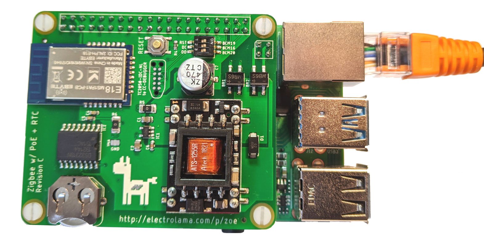
zoe is a 802.15.4/Zigbee development board designed to be used alongside a Raspberry Pi. It follows the Raspberry Pi HAT Mechanical specification but it does not have the ID EEPROM therefore it is not technically a HAT.
The E18-MS1PA Zigbee module used incorporates the CC2530 wireless microcontroller with the CC2592 Range Extender (PA+LNA). This is a fairly common and mature chip combo, famously used by Zigbee2mqtt and other open-source Zigbee systems.
Using the Ag9800MT PoE module, it can power both itself and the Raspberry Pi through passive 48V or IEEE 802.3af Power-over-Ethernet (PoE) for a single cable deployment. Mount your Pi and zoe and just pull an Ethernet cable for both power and comms!
For very accurate offline timekeeping, the DS3231 RTC chip is included as an option.
While a TagConnect to CC-Debugger footprint is included, no external programmer is required for flashing the Zigbee module thanks to flash-cc2531, a bitbanged implementation of the Chipcon programming protocol.
Purchase
Three versions of zoe, in partial kit format, will be available on the Electrolama Tindie Store very soon. Orders ship from London, UK.
A comparison table for the versions listed:
| Radio | RTC | PoE | |
|---|---|---|---|
| zoe-lite | ✔️ | ❌ | ❌ |
| zoe-RTC | ✔️ | ✔️ | ❌ |
| zoe-PoE | ✔️ | ✔️ | ✔️ |
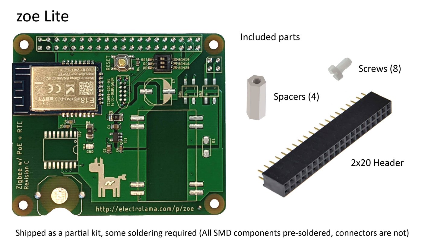
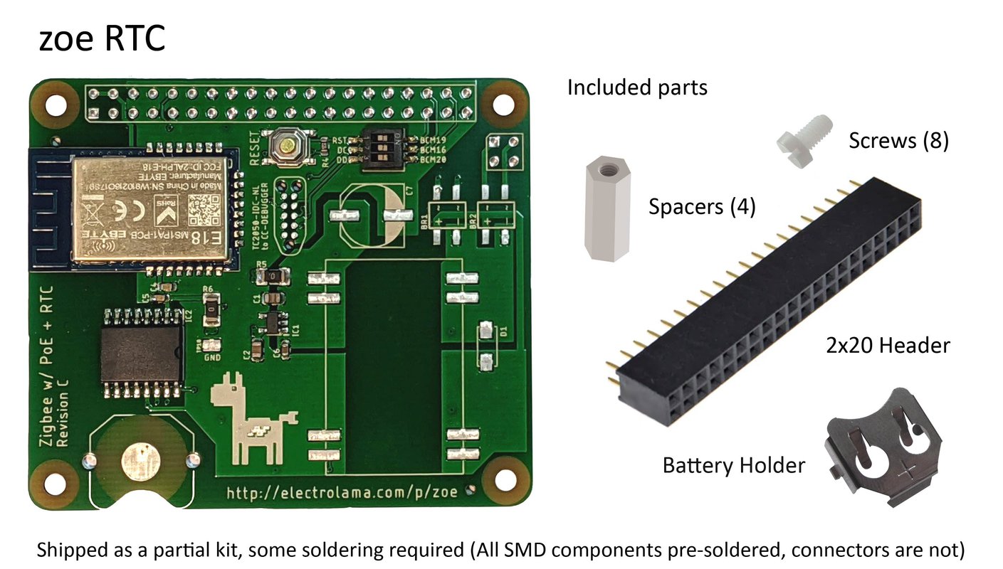
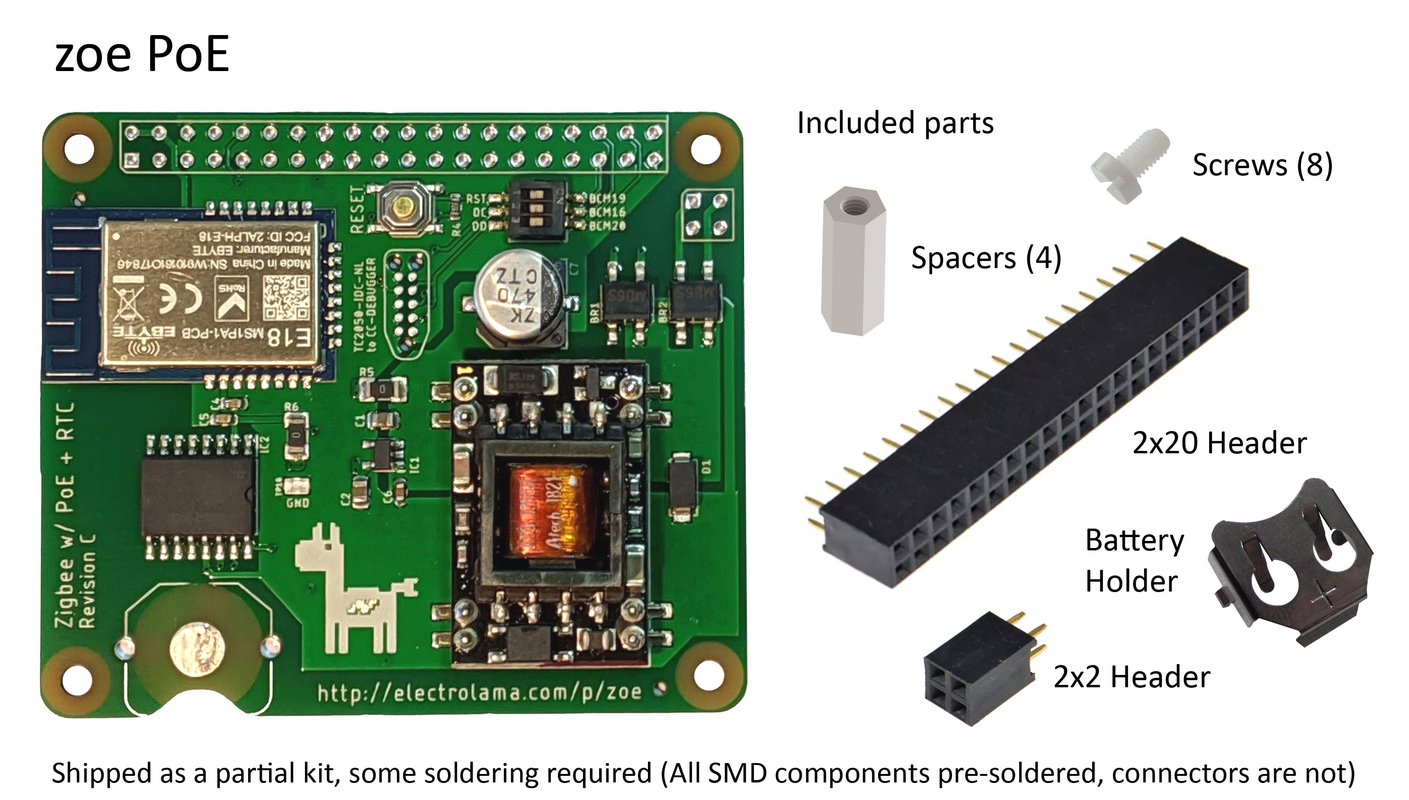
All these ship as partial kits. All SMD components are pre-soldered but connectors/battery holders are not. See below:


Please keep in mind that zoe is a general purpose development board and as such, it is shipped "blank" with no code on the wireless microcontroller. You will need to program it before it does anything meaningful. Given the application dependent nature of this board, limited after-sales support can be provided for Tindie purchases (For example: we can help you program this board but can't fix your Zigbee network range issues or offer specific software support).
Subscribe to the Electrolama mailing list to be notified of project updates and when kits/assembled units go on sale.
User Manual
Getting hardware ready
zoe purchases from Tindie ship as partial kits, with all SMD components pre-soldered and connectors/battery holders that require some soldering.
Here are the recommended steps to complete the assembly of zoe boards:
- Unpack the parts kit and get your soldering iron ready
- Install the battery holder (for the RTC and PoE boards), push it in place and solder it. Best get this sorted before dealing with the headers.
- Position the 2x20 and 2x2 (if you are using the PoE kit) headers on the Pi you will be using and install the hex spacers using the bottom 4 screws.
- Align and push the zoe board on to the connectors placed on the Pi, secure the zoe board on to Pi and the hex spacers using the top 4 screws. The purpose of this is to make sure the zoe board is perfectly aligned with your Pi.
- Solder the connectors in place and inspect your work, make sure there aren't any missed spots or cold solder joints.
If you need some pointers or a refresher about soldering, this YouTube video might come in handy.
Initial Setup on the Raspberry Pi
(Moved here)
Programming the radio (bit-banged, flash-cc2531)
Thanks to the flash-cc2531 tool, you can program the CC2530 radio without needing external programming adapters (typically, a CC-DEBUGGER is used to program these parts).
Please keep in mind that zoe is a general purpose development board and as such, it is shipped "blank" with no code on the wireless microcontroller. You will need to program it before it does anything meaningful.
Make sure the programming switches are in the "ON" position before programming the module

You might notice a piece of yellow/orange tape on top of the DIP switch, peel this off before use.
Before you can use the flash-cc2531 tool, you need to install the wiringpi library dependency:
sudo apt update && sudo apt install wiringpi
Grab the latest version of the flash-cc2531 tool and unzip:
wget -O flash-cc2531.zip https://codeload.github.com/jmichault/flash_cc2531/zip/master && unzip flash-cc2531.zip
You will need a suitable firmware for this board, it is important to note that any firmware used should be compiled for CC2530 with the CC2592 range extender (see module datasheet for the pin connection details).
If you want to experiment with Zigbee2mqtt, the Z-Stack coordinator firmware is a good starting point.
Grab the suitable firmware, or compile your own, and follow the instructions below to program the chip:
Identify the chip
$ ./cc_chipid
  ID = a524.
You should see ID = a524. here, if you don't then make sure the programming switches are in the "ON" position before and try again.
Erase the chip
$ ./cc_erase
  ID = a524.
  erase result = 00a2.
Program the chip
$ ./cc_write CHANGE_THIS_TO_YOUR_OWN.hex
  ID = a524.
  reading line 15490.
  file loaded (15497 lines read).
writing page 128/128.
verifying page 128/128.
 flash OK.
Be aware that this bitbanged programming method is a lot slower than the CC Debugger and it might take minutes, instead of the usual seconds, to burn your program.
A useful note, if you're building your own zoe boards: E18 modules are shipped from the factory with code protection turned on, meaning that you won't be able to program them without an erase cycle first. If programming is failing, it is a good idea to erase the device first. This is not an issue for zoe boards sold by Electrolama as they are erased at the end of the production test.
To reset the chip after programming, press the RESET pushbutton on the board or use the following little program to toggle the GPIO that the reset pin is connected to:
#include <stdio.h>
#include <wiringPi.h>

int pinRST=24;

int main()
{
    if(wiringPiSetup() == -1){
        printf("no wiring pi detected\n");
        return 0;
    }

    pinMode(pinRST, OUTPUT);
    digitalWrite(pinRST, HIGH);

    printf("ok\n");

}
Compile with gcc -Wall -o modreset modreset.c -lwiringPi and run to reset the module.
It is a good idea to return the programming jumpers back to the "OFF" position after programming the module for the normal operation of the device. We don't want stray GPIO toggles interfering with the operation of the module.
Programming the radio (using CC-DEBUGGER)
If you happen to have a CC-DEBUGGER and a TagConnect TC2050-IDC-NL cable handy, you are in luck! Just plug in the TagConnect IDC end to the CC-DEBUGGER and hold the pogo-pin end on the contact pads on zoe while you program the board. No adapters necessary, it's just a straight connection! Neat, eh?
Using the RTC
Set RTC driver up (as root)
# echo ds1307 0x68 > /sys/class/i2c-adapter/i2c-1/new_device
Update the system time
$ sudo apt install ntpdate && sudo ntpdate -s 0.pool.ntp.org
Write system time to RTC
$ sudo hwclock -w
Read date/time back from RTC
$ sudo hwclock -r
You'll probably want to integrate this in your init scripts.
Power-over-Ethernet
zoe uses the Ag9800MT PoE module from Silvertel, which is IEEE 802.3af compliant and has an input voltage range of 36V to 57V with short-circuit and thermal protection. It can provide up to 9W of 5V power to power both the Raspberry Pi and zoe itself, which is plenty enough for most workloads on a Raspberry Pi (except when you have power hungry external devices hooked up).
If you have a IEEE 802.3af compliant PoE switch, powering a Raspberry Pi with a zoe board attached is as simple as just plugging an ethernet cable on both ends. The PoE module cleverly generates the PoE compatibility signature required by the Power Sourcing Equipment (PSE). If you have passive PoE equipment, you will have to manually enable 48V power (24V won't work) on the port that the Raspberry Pi with zoe installed is connected to.
Tested PoE Switch/Adapters
Below is a list of tested configurations, feel free to send a pull request with your test results or ping @OmerK.
| PoE Switch/Adapter | PoE Type | Status |
|---|---|---|
| NETGEAR ProSafe GS108P | 802.3af | ✔️ |
| AliExpress Mystery Meat PoE "Injector" Wall Plug | Passive 48V | ✔️ |
Zigbee2mqtt Configuration
Correct serial comms settings for Zigbee2mqtt configuration.yaml are:
Configuration
serial:
  port: /dev/ttyAMA0
advanced:
  rtscts: false
The rtscts: false directive does not appear in the default configuration file but is crucial for the operation of zoe so please don't ignore that. Also note that it sits in the advanced: config group and not in serial:.
Troubleshooting
"Error: Failed to connect to the adapter (Error: SRSP - SYS - ping after 6000ms)"
This is a general error if there are communication problems with the adapter used.
A checklist to go through if you get this error message:
- Make sure you have the correct serial port and
rtscts: falseoption set in yourconfiguration.yaml - Make sure you have the correct firmware burned on your adapter. Remember, zoe boards ship blank so you will need to burn the appropriate firmware before using it with any application.
- Are you using any virtualisation/container pass-through for the serial port? There have been reports of these potentially causing problems so for debugging purposes try communicating with the adapter directly from the host OS it is connected to (i.e: see if it works without the bypass)
- Make sure you are using an up-to-date version of Zigbee2mqtt on the host and firmware on the adapter.
Downloads
- EAGLE source files in electrolama/zoe
- Schematic (pdf), Revision C
- Local copy of the E18 Zigbee module datasheet (If you're looking for details of how CC2530 and CC2592 are connected inside the module)
Changelog
In the repo, click here.
License
zoe is designed by Electrolama / Omer Kilic and licensed under the Solderpad Hardware License 2.0.
Regulatory Notice
This kit is designed to allow Product developers to evaluate electronic components, circuitry, or software associated with the kit to determine whether to incorporate such items in a finished product and Software developers to write software applications for use with the end product. This kit is not a finished product and when assembled may not be resold or otherwise marketed unless all required FCC (or any other local authority) equipment authorizations are first obtained. Operation is subject to the condition that this product not cause harmful interference to licensed radio stations and that this product accept harmful interference.
Contact
For general enquiries, suggestions and errors spotted: Email us at hello@electrolama.com. Community contributions to these pages are very much encouraged so you could also send pull requests on the documentation repo (source of these pages) with your proposed changes.
For support regarding Tindie purchases: support@electrolama.com. Please note that we do not monitor Github issues or third party forums for customer support.