Overview
NANDCat is an SAO compatible logic gate demonstrator/cute badge accessory.
NANDCAT IS ALIVE!
— Omer Kilic (@OmerK) November 5, 2019
Will put design files and BOM up online in a few days.
It's SAO compatible and I'll pack a handful of them for Supercon next week, find me if you want to home a NANDCAT 😺 pic.twitter.com/qNjOtDVKzT
The output (LED: D1) is a function of the inputs (Pushbuttons: SW1, SW2), here's the truth table for a NAND gate:
| A (SW1) | B (SW2) | Y (D1) |
|---|---|---|
| 0 | 0 | 1 |
| 1 | 0 | 1 |
| 0 | 1 | 1 |
| 1 | 1 | 0 |
The artwork is by @psd, who kindly let me turn it into a silly PCB. Thanks, Paul!

Schematic

Bill of Materials
| Designator | Part | Description |
|---|---|---|
| SW1, SW2 | Omron B3S or similar | 6mm SMD SPST-NO Tactile Switch |
| Q1, Q2 | BC847B or similar | NPN Transistor, SOT23 package |
| R1, R2, R4 | 1kΩ | Generic 0603 resistor |
| R3, R5 | 100kΩ | Generic 0603 resistor |
| D1 | 3mm LED | Generic LED, diffused lenses are better |
| J1 | 2x3 100mil header | Generic header |
| BAT1 | Keystone 3034 or similar | SMD 20mm coin cell holder |
SW1 and SW2 use the ubiquitous 6mm SMD pushbutton footprint, the Omron part is for reference only and there should be many other, cheaper, parts that can be used there. Same goes for BAT1.
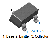
Q1 and Q2 can be pretty much any NPN transistor in SOT23 package that has the following pinout:
Go crazy with your LED choice and decorations!
NANDCat goes to a rave! pic.twitter.com/tQ8k387pwV
— Omer Kilic (@OmerK) November 16, 2019
Downloads
- KiCAD source files in electrolama/nandcat
Changelog
- Revision A (Oct 2019)
- Initial release.
- Revision B (Nov 2019)
- Added a battery holder (CR2032) and some exposed copper for a brooch/pin back.
Contact
Ping @OmerK